HackEEG 32 Channel Configuration (Four Boards)
We recommend getting HackEEG working in a single-board configuration (see HackEEG Hardware Configuration) first. This will allow you to become familiar with the hardware and software before moving on to the more complex 4-board configuration.
Once you have HackEEG working with one board, you can then do the following to get 4 boards working.
You can use the HackEEG directly connected to a laptop, or connected to a Raspberry Pi to stream data wirelessly.
IMPORTANT: FOR SAFETY REASONS ONLY USE HACKEEG WHEN CONNECTED TO BATTERY POWER!
This includes any laptop or other computer– all systems must be battery powered only. HackEEG has no mains isolation circuitry.
HackEEG and the TI ADS1299 EEG system-on-a-chip are static sensitive devices. Wear a grounding wrist strap when working on these systems.
To assemble your system:
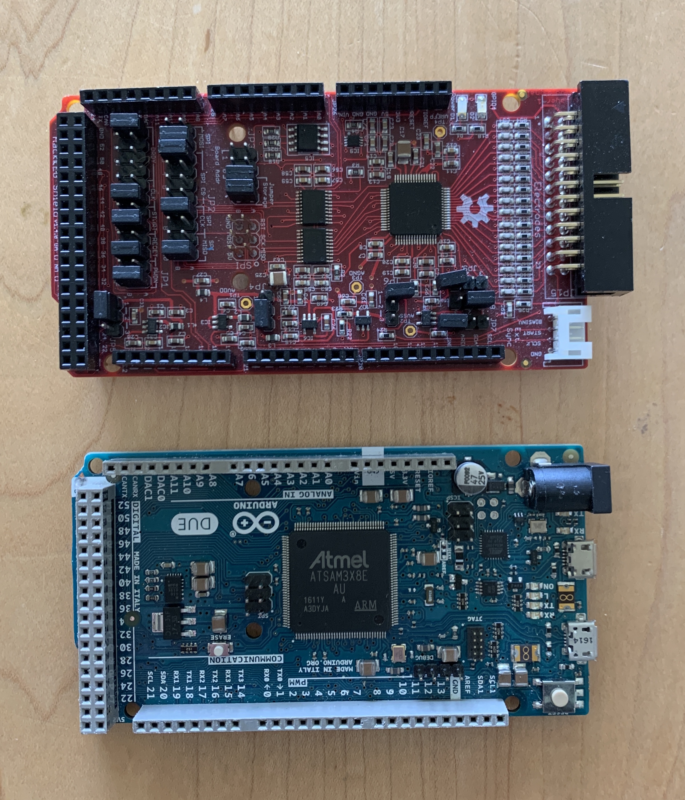
Take the HackEEG boards out of their static-protection bags, and take the Arduino Due out of its box. Remove the protective foam from the HackEEG bottom pins. The boards should look like this:
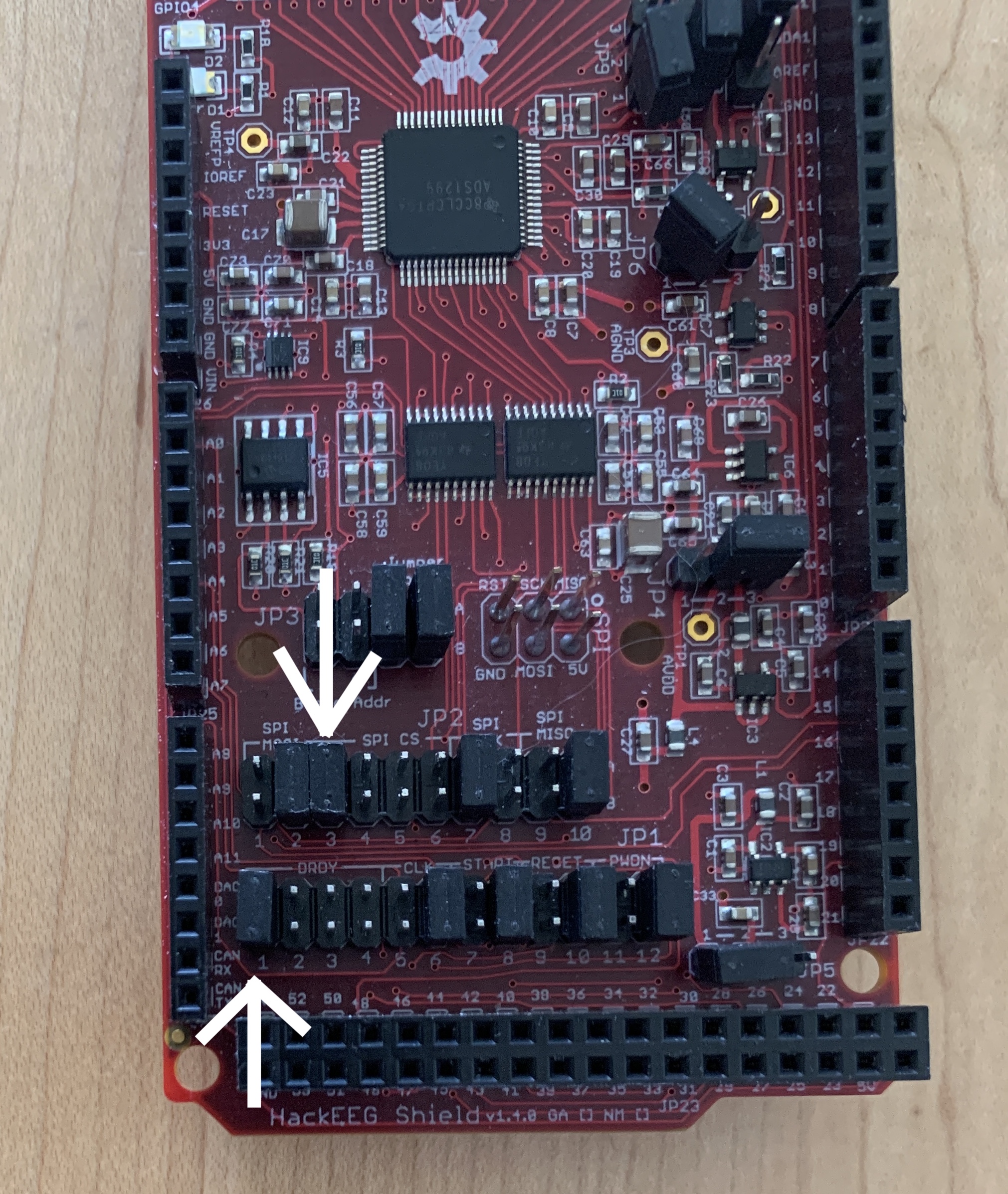
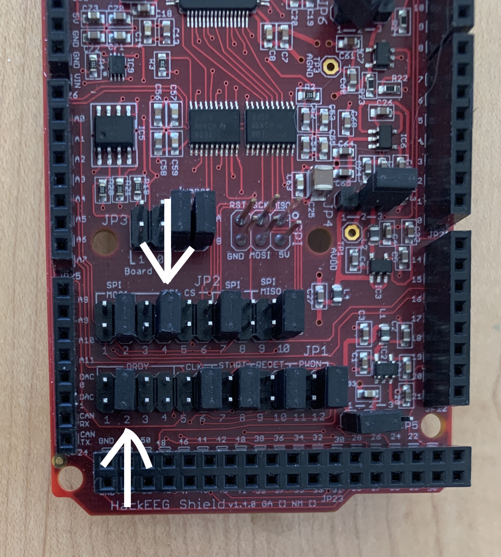
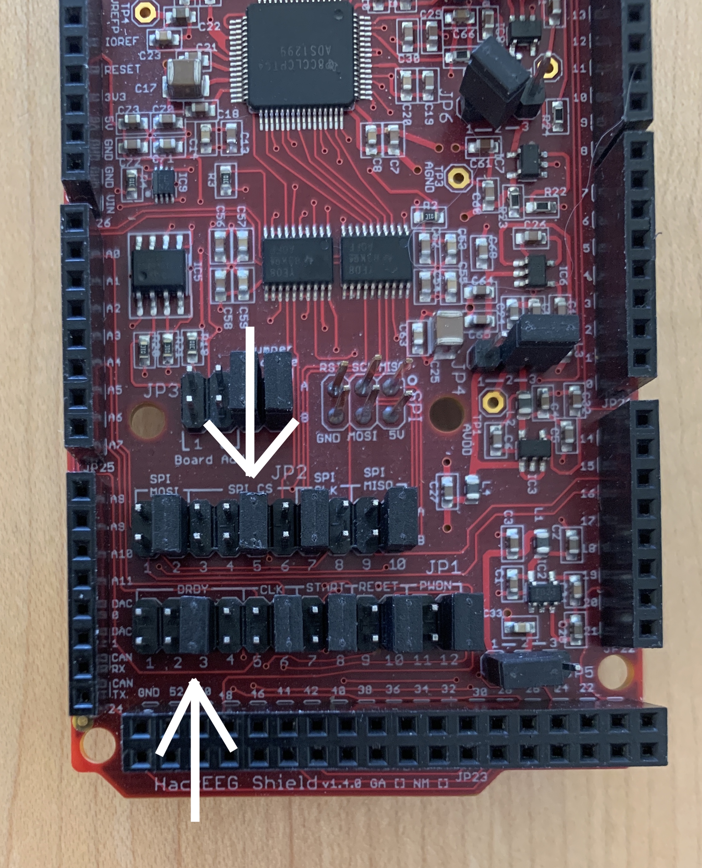
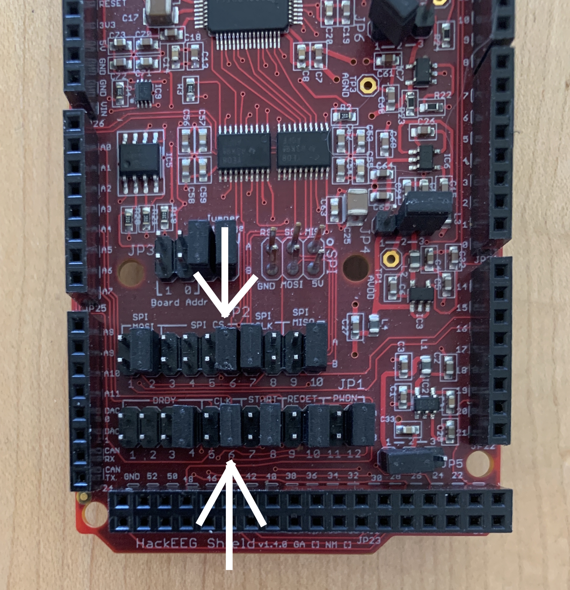
Configure the boards for use in a 4-board stack. The HackEEG boards come configured for a single-board configuration. Boards in a 4-board stack are numbered 0-3. Board 0 is on the bottom, 3 is on the top. The SPI CS (Chip Select) and DRDY (Data Ready) jumpers need to be changed for boards 1, 2, and 3. Board 0’s configuration is ok as-is.
In the photos below, the CS jumper is on JP2 in the top row of jumpers, positions 3-6. DRDY is in JP1 on the bottom row, positions 1-4. The white arrows indicate the correct jumper positions.
Board 0:
CS jumper: JP2 Position 3 (leave as-is)
DRDY jumper: JP1 Position 1 (leave as-is)
Board 1:
CS jumper: JP2 Position 4
DRDY jumper: JP1 Position 2
Board 2:
CS jumper: JP2 Position 5
DRDY jumper: JP1 Position 3
Board 3:
CS jumper: JP2 Position 6
DRDY jumper: JP1 Position 4
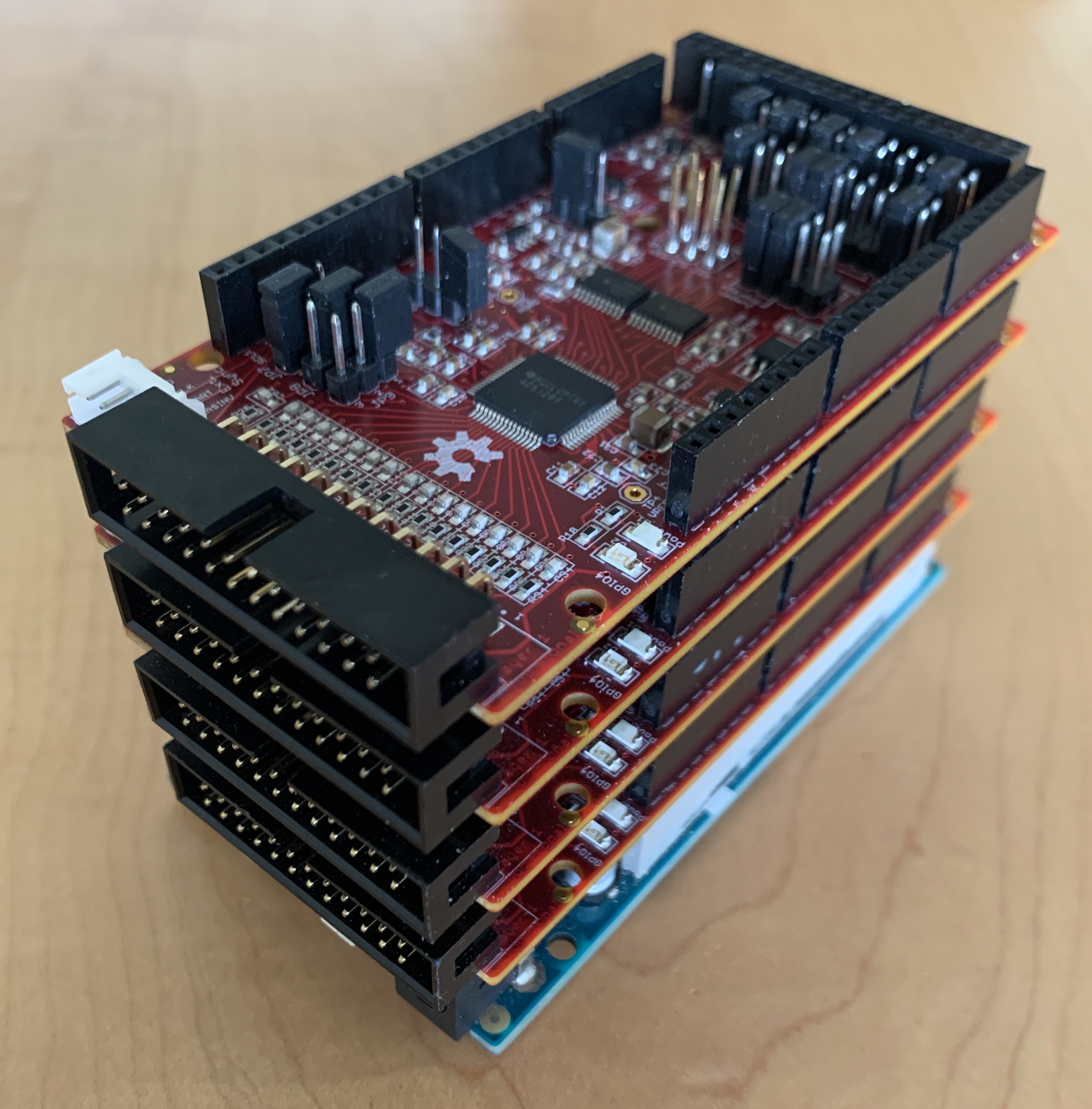
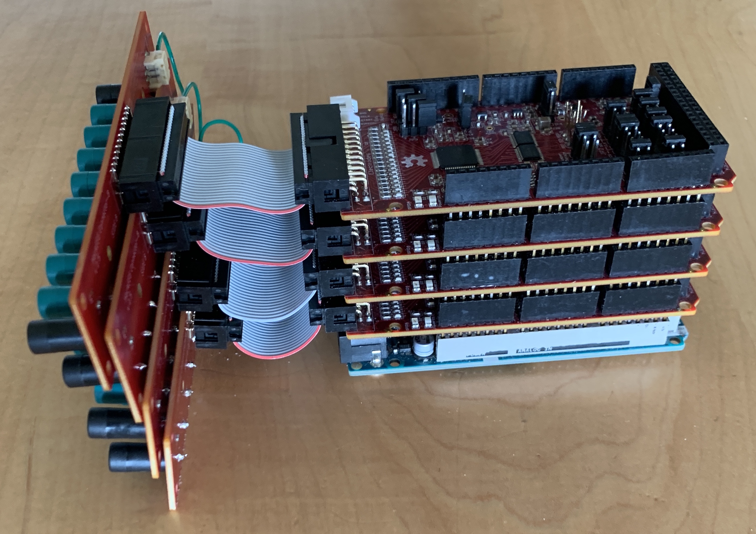
Carefully mate the boards together, being careful to not bend any of the long pins. You may need to press hard to get the connectors to seat correctly.
They should look like this:
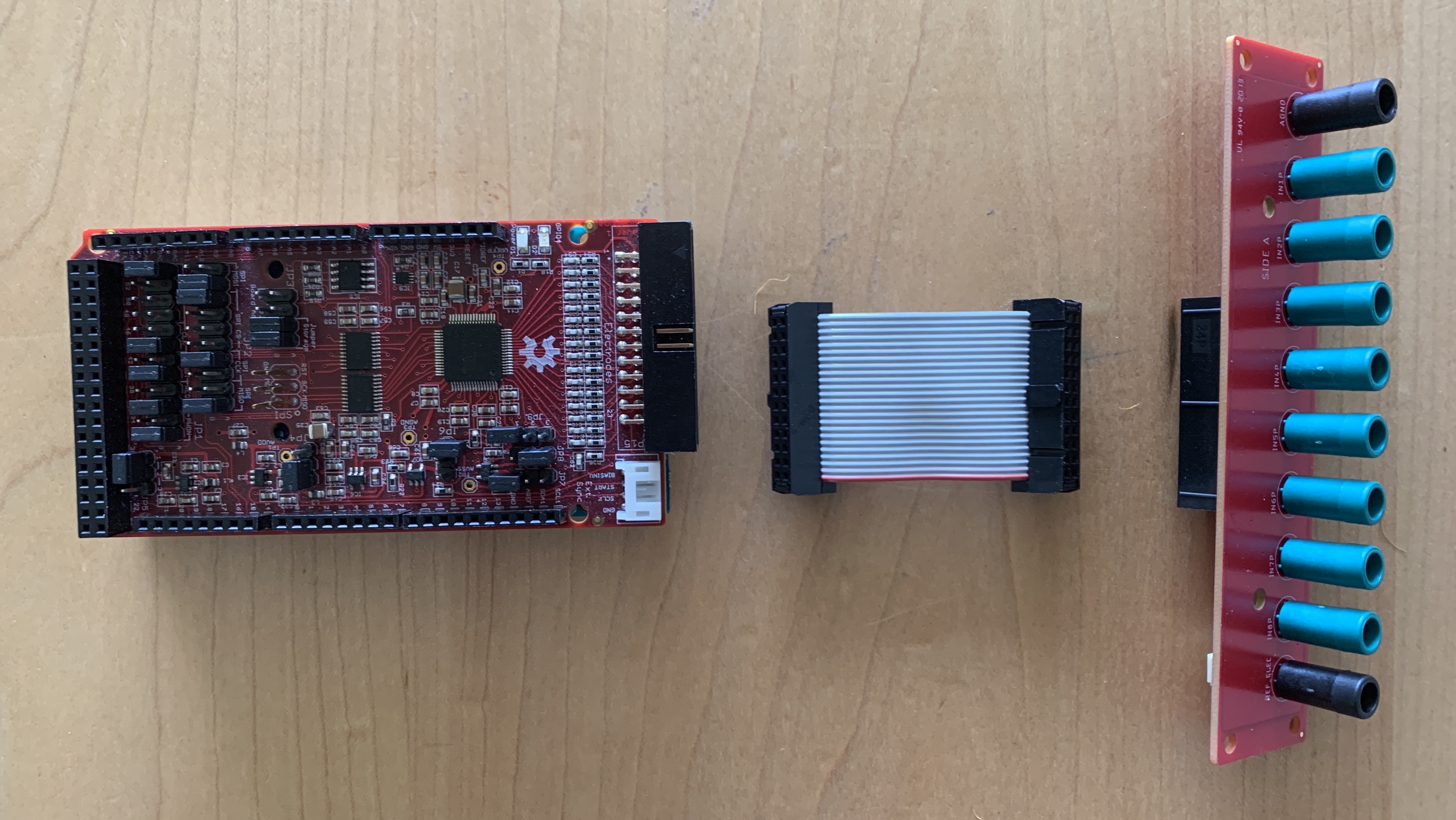
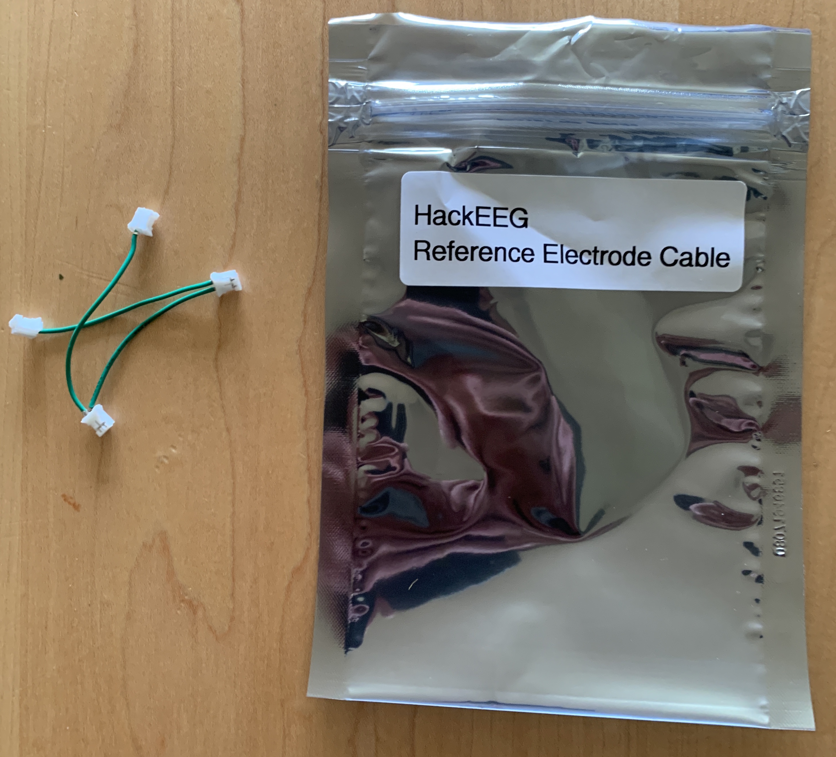
Take the connector boards and ribbon cables out of their bags:
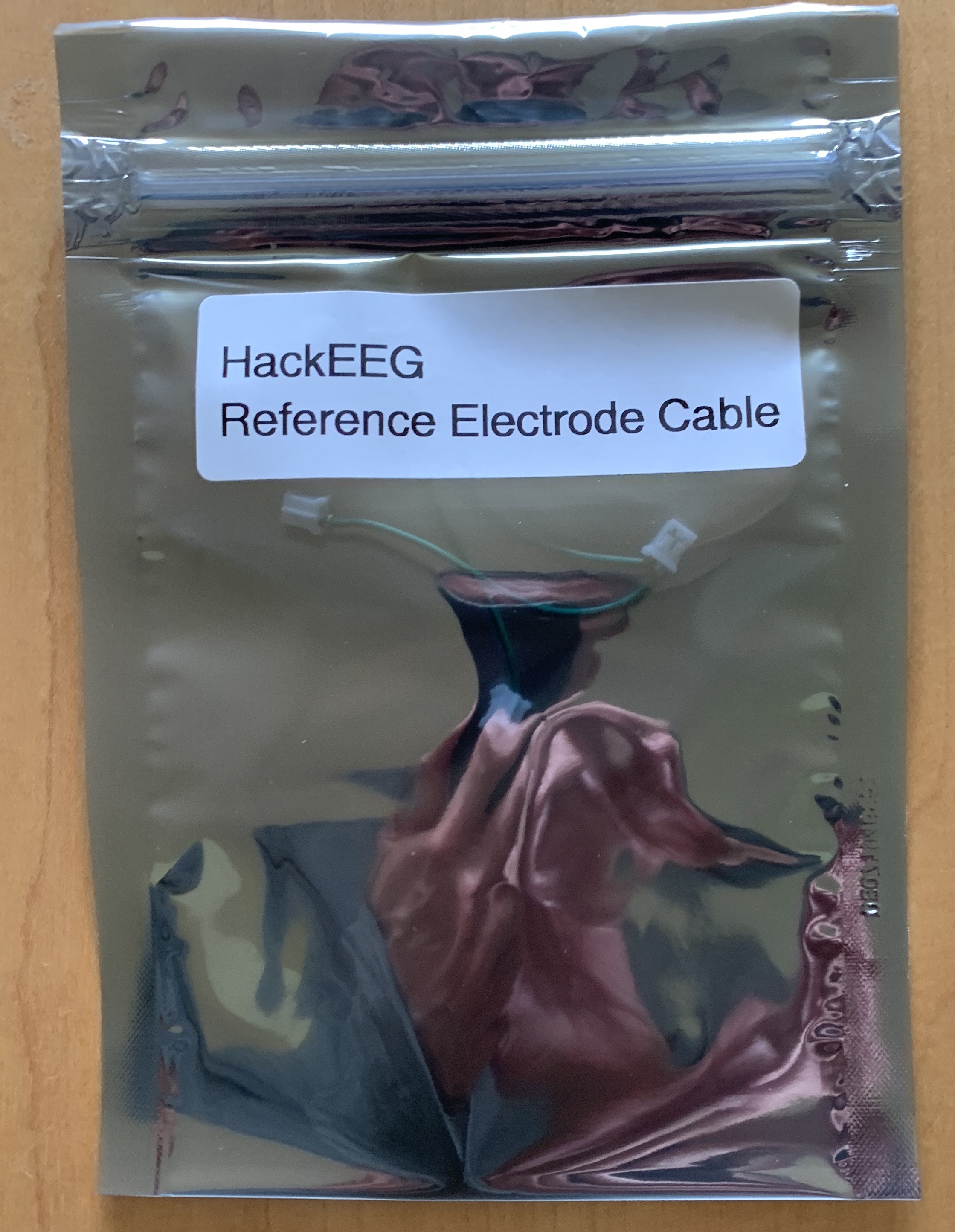
Find the HackEEG Reference Electrode Cable. This cable connects the Reference Electrode on all four boards together, so you only need to use a single reference electrode.
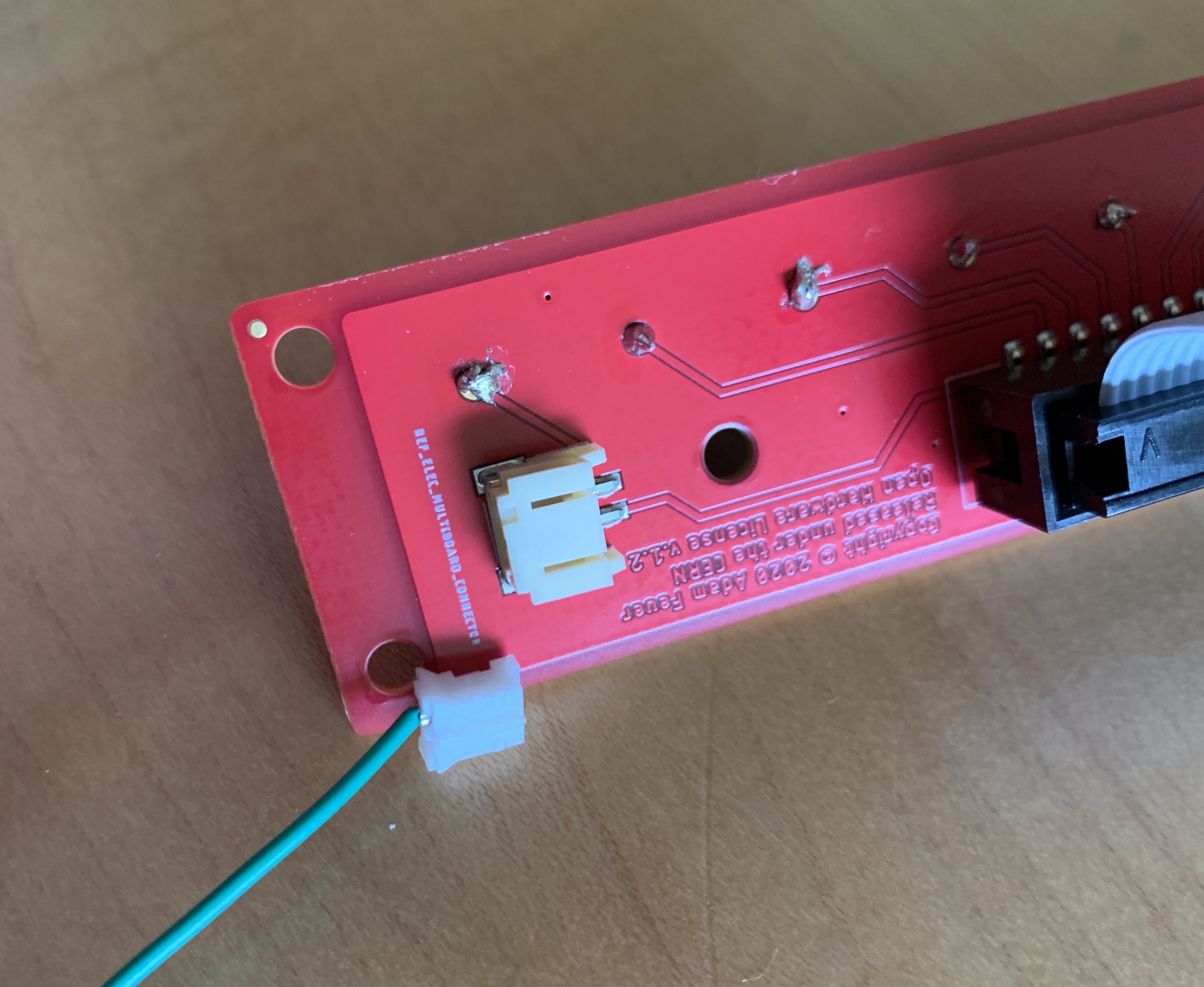
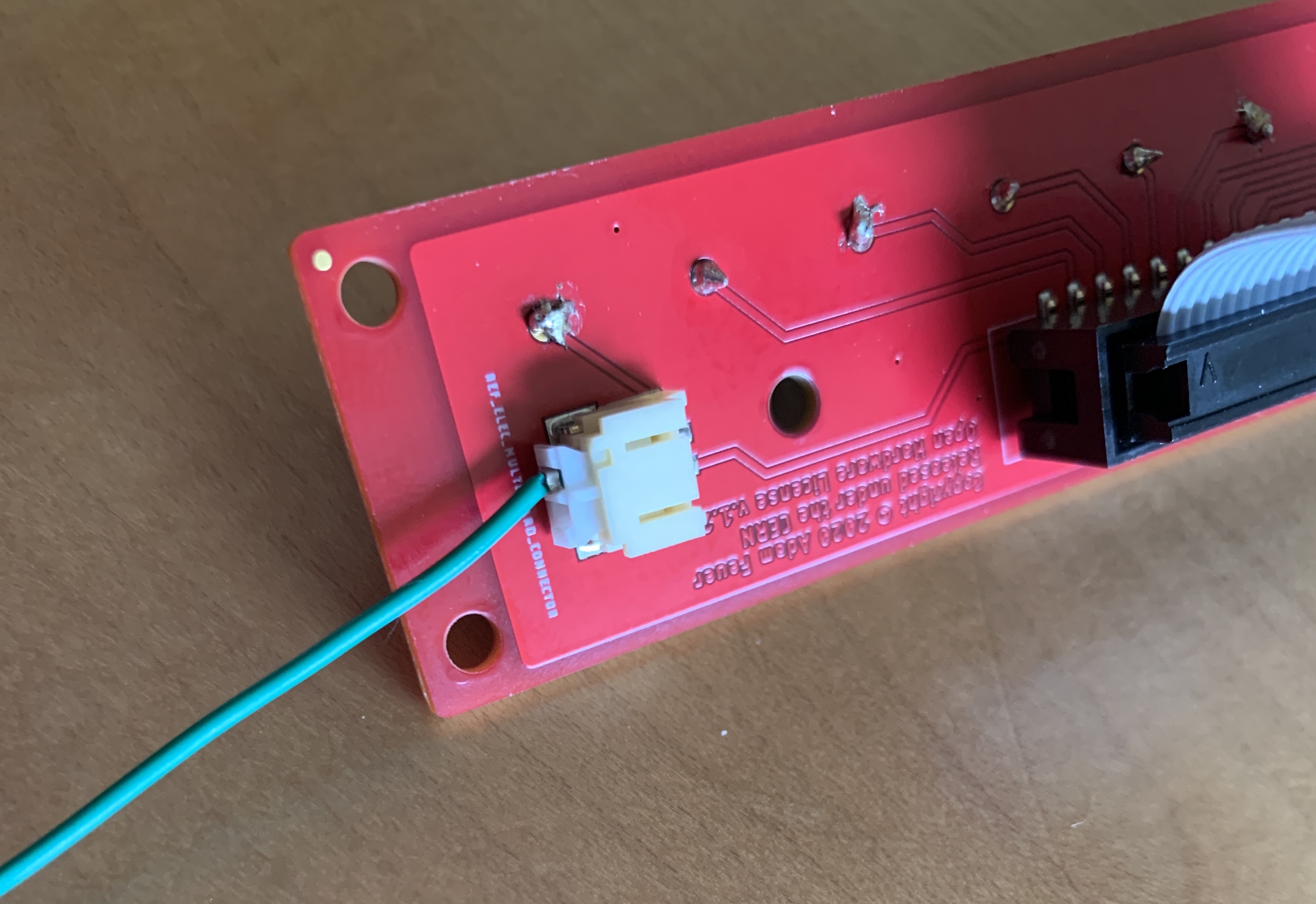
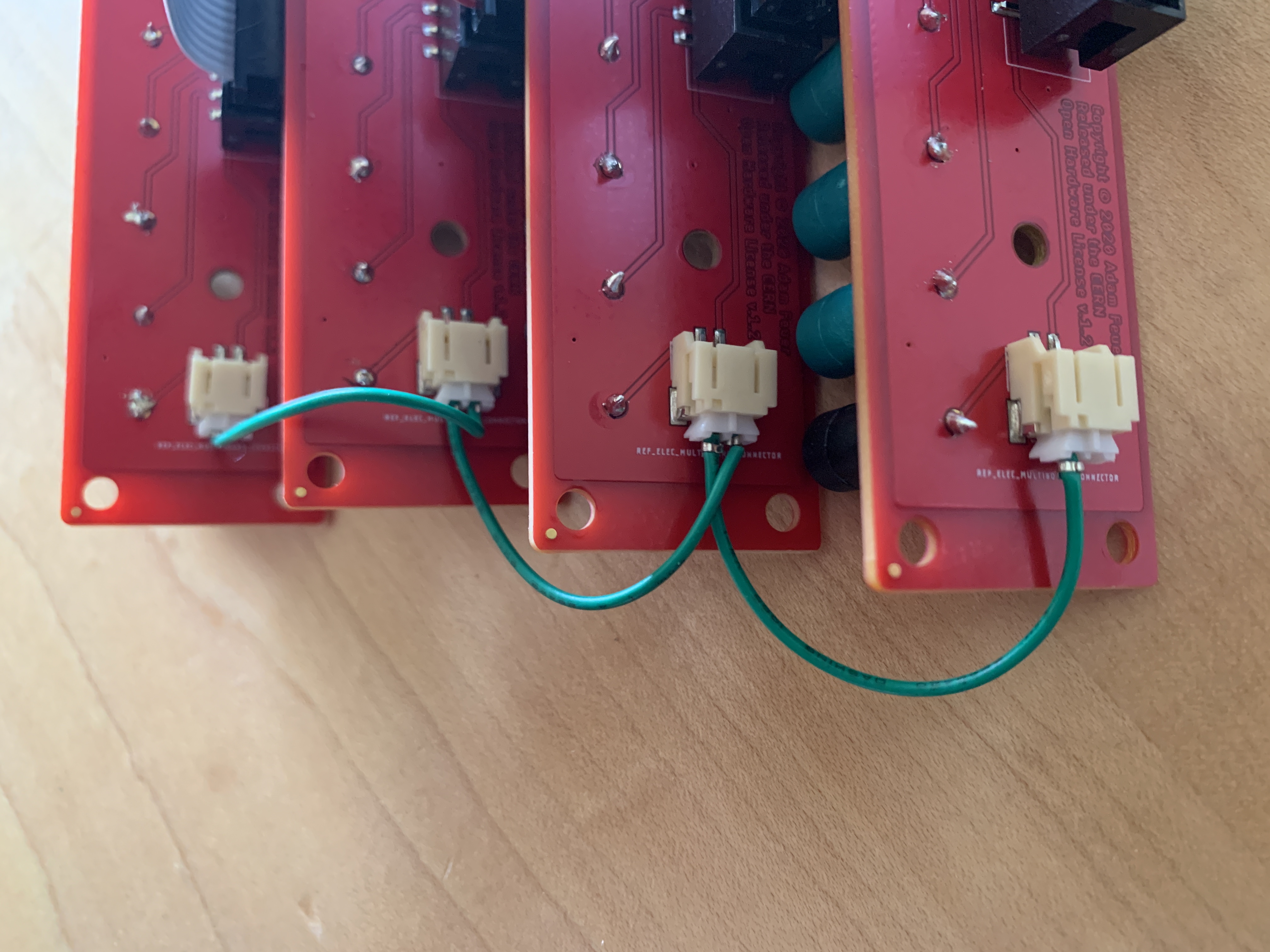
Connect the connector boards together using the Reference Electrode Cable. The cable is keyed so it will only go into the connectors one way:
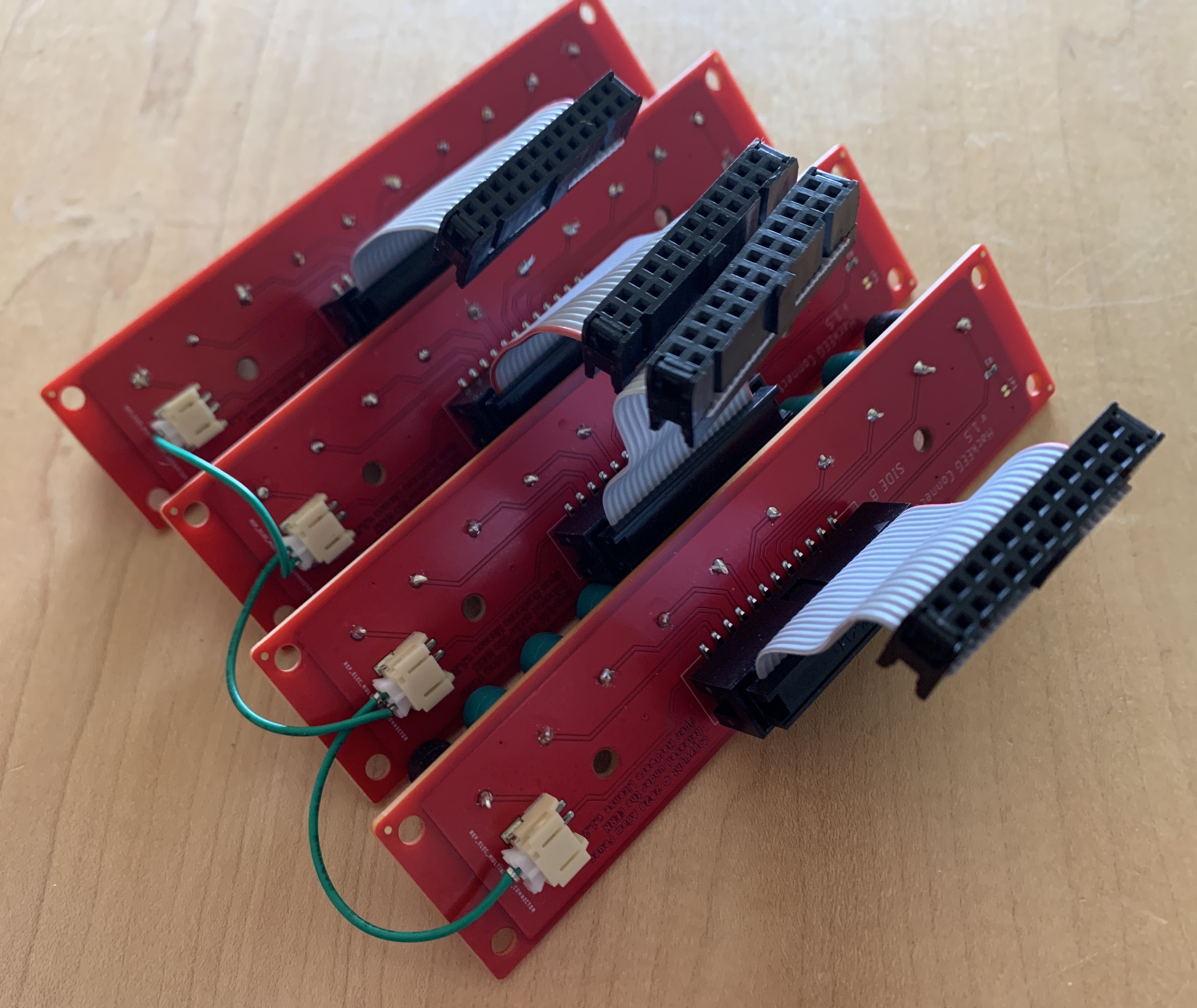
Connect the HackEEGs and connector boards with the ribbon cables. The cables are keyed so they will only go into the connectors one way:
If the ribbon cables are too short for your application, please contact Starcat and we’ll make you longer ones.
Laptop Setup
Use one of the two MicroUSB cables, plug one end into the Arduino Due’s Native Port (marked on the bottom of the Due). Plug the other end into the laptop.
You should see the red power LED light up on the HackEEG.
You may need to use an external USB battery plugged into the Arduino Due’s Programming Port if your laptop does not provide enough power to the HackEEG stack. NEVER USE A USB POWER ADAPTER PLUGGED IN TO MAINS (WALL) POWER!